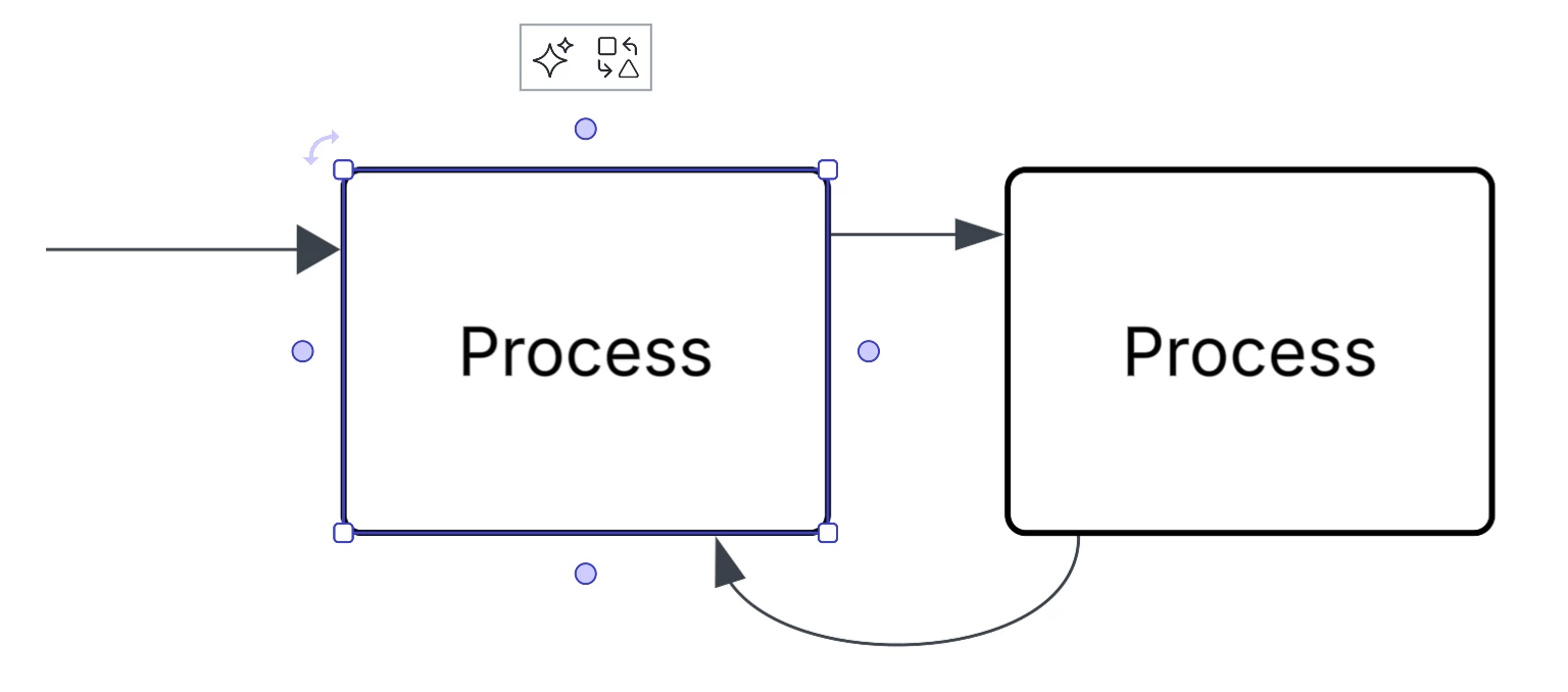
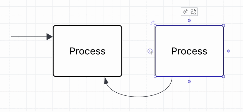
Future Consideration

Create custom connection points

Related products:Lucidchart
  • December 27, 2023
  • 31 replies
  • 1242 views

Show first post

Comments

Ambar D
Forum|alt.badge.img+12
  • Lucid community team
  • July 14, 2025

Hi ​@Erik Gaudin, thank you for adding your feedback to this thread! While we don’t have a roadmap that is available to view, I can ensure you that our product team is regularly reviewing comments and feedback just like yours within this space as they continue to research product enhancements and new features. 

Your feedback is incredibly valuable to us so thank you for taking the time to let us know what you’re hoping to see here! 

I would recommend checking out the Release Notes section of the community for the latest updates on new features. You can click Subscribe to get notified of new posts if you want to stay up to date! 

Release notes are updated monthly for the Lucid Suite, Enterprise Shield, and the Lucid Accelerators. Admin panel release notes are updated quarterly.  


Forum|alt.badge.img

In my day to day work I think the ideal way to implement this is to have an option to edit the stencil/object.   Once in the edit dialogue you can have an “Add Connection Points” option that allows the addition of a point object.   The save dialogue could allow you to save it to you chosen shape library with the option to replace.


Forum|alt.badge.img

As LucidChart licence grow in price.. over and over… It’s start to not make sence for us to have migrate all of our Visio Licence to LucidChart… 3 Yr ago, LucidChart were cheaper than their direct competitor, now it’s not.. and pricing are still growing. Working without that feature, for pricing difference were… acceptable..


Now.. we start questioning ourself.


Ambar D
Forum|alt.badge.img+12
  • Lucid community team
  • May 5, 2026

I certainly understand why this is important to your workflows, and I appreciate you both ​@Robert Parrish and ​@Erik Gaudin for taking the time to leave your feedback and let us know what you’d like to see. 


While I know this is not exactly what you’re hoping for, and I understand that it does not address pain points with very technical or complicated diagrams, I’d like to explain somewhat of a workaround in case it’s helpful to any users hoping to simply customize where lines land on shapes. As shown in the image below, you can connect arrows to specific parts on shapes even without additional custom connection points.

You can do so either by (1) creating a line out from an existing connection point, then dragging it to another part of the shape, or (2) dragging a line from the standard shape library directly onto where you’d like it on a shape.

(1) Create a line from an existing connection point and drag it elsewhere on the shape
(2) Drag a line from the Standard shape library onto a desired part of the shape directly.


Thank you again to everyone who has commented here with your thoughtful and detailed feedback! I certainly understand that many in this thread are hoping for the ability to add custom connection points added to shapes or images, and that the workaround above does not fully meet this need.


We encourage anyone else who’s interested in this to upvote this post and share any additional details about your use case or what you’d like to see in this experience. 

For more information about how we manage feedback in this community, please take a look at this post:


Forum|alt.badge.img

Sorry but, we already know that, like Microsoft Paint, can draw line anywhere we want.

But it seem you didn’t understand why the custom connection points are important. Like any drawing application, your customer are not only doing basic diagram, reason why you allow to import model and template in user space.


Most IT, and technical user know what is a custom connection points, and their real benefith.


In case you don’t know, most vendor create template of what they are selling (like Cisco, Arista, IBM, VmWare) for Visio. template like this example : You have a UCS frame, Nic port, and add-on to UCS frame


So you can insert those item in grey spot (for the UCS Frame), and for the NIC, you can attached directly to the NIC port the cable… not “somewhere near that”.. on the port it self, because a connection point exist.

If the NIC, is at the center of the frame, it will be hard in LucidChart to acheive, because the connexion will attempt to be done on the frame.. not the NIC

Here another divice, that have 3 NIC, 1 serial, 1 VGA and 2 USB (to be added to the Cisco Frame)

0_0?a=104&x=825&y=-181&w=335&h=31&store=1&accept=image%2F*&auth=LCA%207098d54732d5e448bcca7a994ee1c5a4df459edf439b2208b8a0c2d51bcde113-ts%3D1778071139


Here a switch blade for a Cisco Frame . How do you, perfrectly attached a wire at the center of each of those beautifull port, without connextion point ? 

And manually move all of them to “look like” they are all in their port, is super long, require lot of zoom in/out, and at the end, look like not alligned at all. Connexion point at the center of each Network port, ensure all line we will draw, will be nice to show to other, and not look like a child drawing.


So the goal here, is to help Lucid Chart evolve their product in a way they will be perfect for all customer type.. those that only did basic diagram, and those that are doing very detail “techhnical” diagram. The dream of any large enterprise (like mine), is to have one tools to fit all. That “custom connexion point” will be the last missing part to ditch lot of other tools we are using.


Ambar D
Forum|alt.badge.img+12
  • Lucid community team
  • May 6, 2026

Thank you for these details ​@Erik Gaudin!

Your visual examples really help to illustrate just how important this is and how much it would improve your experience, so I appreciate you taking the time to let us know what you’re hoping to see. I understand how dragging lines to different parts on a shape does not work for your use case and for many technical diagrams.

Comments in this space are used as a repository of feedback for our product teams as they continue to research new features and enhancements. Thank you for being part of this feedback process!